The latest wiring instructions manual is here.
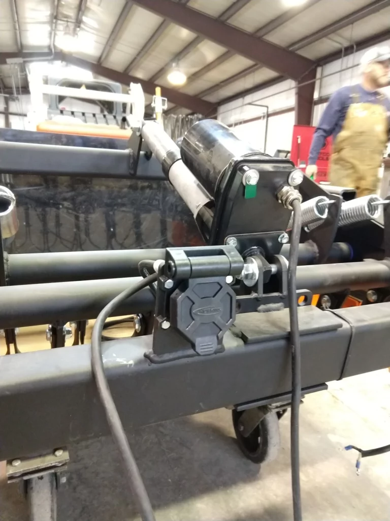
Note on Actuator Direction: The knife section actuator should be mounted in the reverse direction (as shown in the photo header on this page) so that the wire routing is minimized. Unless it was delivered pre-wired, your Ginzugroomer knife section actuator was delivered from the factory with the motor end of the actuator towards the back of the groomer, leaving the shaft facing downward to prevent water from seeping past the shaft seal and into the gearbox of the actuator. When running the wire to the RV connector, it is better to reverse the actuator direction to minimize wire length and the potential that it may catch and break in the mechanism of the knife section.
Fuse or Breaker: 20A “almost” works. You may have good luck with a 20A slow blow fuse. 30A is recommended.
Wire recommendations: Though it is usually possible to use only the wire that is already attached to each actuator, in some cases a longer length will be required. YTS recommends 14 gauge, 2-wire (14-2) stranded rubber-coated cold-rated wire. You may find a 14-3 cold-rated extension cord at your local hardware store for a lower cost than the equivalent length of 14-2 cut from a roll of wire. The actuator wires can be routed along the inside of the aluminum c-channel rails to each tracksetter. We recommend adding a water-resistant 2-wire pigtail connector somewhere in wire to each tracksetter actuator so that the actuator can be removed as required without cutting the wire.
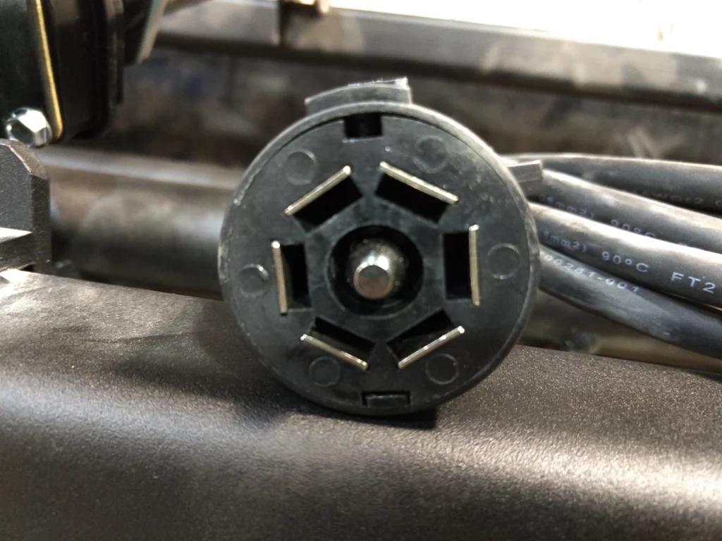
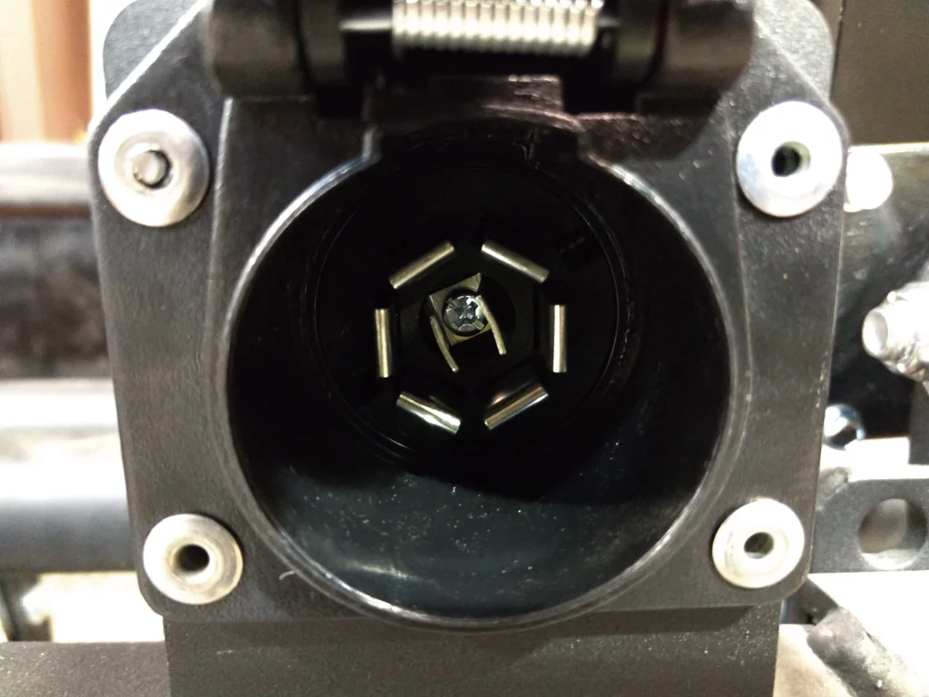
Socket – mounted on groomer. Starting at top center, pin 1 is to the left and pin 6 is to the right of the top center location. This connector is able to support the knife section actuator and two tracksetter actuators. Left is identified from facing in the direction it will be towed. Most customers will only use a single tracksetter per ginzugroomer.
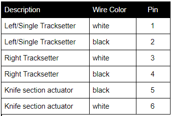
Plug – on the end of the pigtail cable. Pin 1 is to the right, pin 6 is to the left, so that pin 1 of the socket matches pin 1 of the plug. The pin positions may be embossed on the inside of the connector.
Installation
- 8 waterproof crimp ring terminals
- Small heatshrink (may not be required)
- Large heatshrink tubing
- Hair dryer, heat gun, or lighter/match
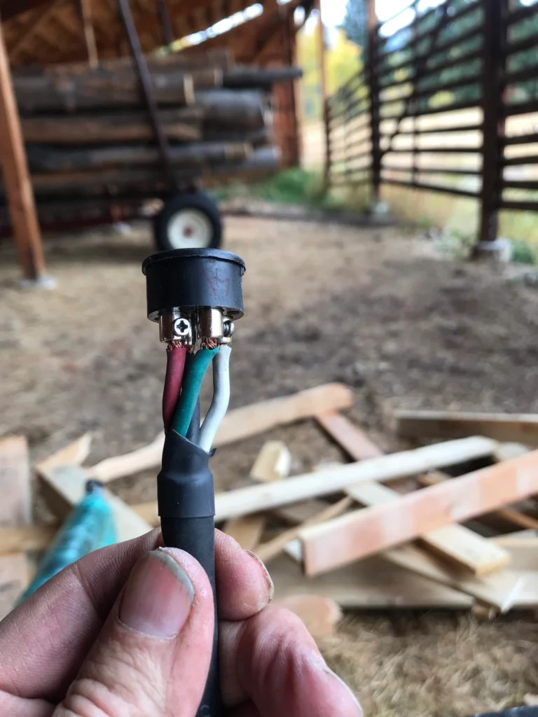
- Cut a 2” long strip of the large heatshrink tubing and put it over the end of the wire and slide it down a foot or so away from the end of the wire.
- Strip each wire back about ¼”. Crimp a ring terminal to the end of the wire. Use a heat source to shrink the tubing around the wire. This protects it from future water intrusion and/or corrosion problems.
- Slide exterior of RV connector housing around wire so that it is ready after the next step.
- Screw ring end of wires from previous step to proper terminals on the RV connector, following the descriptions for each side at the top of the page.
- After wires are screwed down tight, slide the large heatshrink tubing so that it covers the wires just installed, or is as close to covering the wires as you can easily push it. Use lla heat source to shrink the large tubing around the wires.
- Install RV connector housing
- Repeat for the mating RV connector.
Ginzugroomer Wiring
Follow the pinout for the RV connector that is described in the first part of this document. We recommend reversing the usual direction of the actuator such that the motor end is nearest the connector. This direction simplifies the routing of the wiring. The negative aspect of this direction is that water can drip along the shaft of the actuator and enter its gear housing, eventually resulting in rust and early damage.
Tracksetter Connector
The 2-pin connector should be installed anywhere along the wire to the tracksetter actuator. This is included to allow for ease of maintenance and wire disconnecting if you ever need to remove the tracksetter actuator for any reason.
If you have an Arctic Cat Bearcat GS
Bearcat 4-pin connector
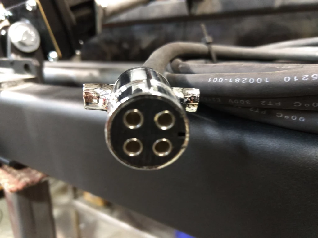
The correct part number for the connector is Napa 755-5040. It is best to buy this connector from Napa. A part that looks very similar to the Napa part is available from other sources, but it doesn’t fit correctly. Pin 1 is to the right of the top center of the photo. Pin 4 is to the left.
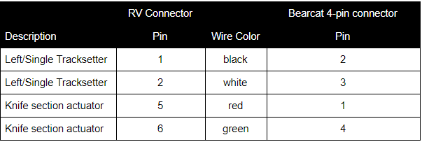
The pinout of the Bearcat connector makes more sense when you realize the top two pins (1 & 4) are the knife section and the bottom two pins (2 & 3) are for the tracksetter.
